Category Archives: Windows Server
How to transfer FSMO Roles From a Failed Domain Controller…
Posted by on March 25, 2019
In case domain controller, which owns FSMO (Flexible Single Master Operation) roles, is fail (virus attack, fatal software problems or catastrophic hardware failure etc.), then you need to transfer FSMO roles from a failed to an another (additional) domain controller (for proper Active Directory domain functioning). Consider this tutorial on how to do it.
Transferring FSMO Roles From a Failed Domain Controller
Suppose, in our Active Directory domain there are 2 domain controllers, that is running Windows Server 2012 R2:
- PDC – dc1.root.contoso.com
- Secondary DC – dc2.root.contoso.com
After the failure of the DC1, we need to seize the FSMO roles from DC1 to a secondary domain controller. Then, on DC2, we need to delete all references to the old controller dc1.root.contoso.com.
Important! Before you begin, make sure your acc

ount is a member of a following AD groups: Domain Adminsand Schema Admins.
Connect to a DC2 and run elevated command prompt (it is recommended to perform all actions on the domain controller, to which you want to transfer FSMO roles). Make sure that this domain has two domain controllers:
dsquery server -forest
Then check which domain controller is the owner of FSMO roles:
netdom query fsmo
You can see that the owner of all FSMO roles is dc1.root.contoso.com

Transferring roles is performed by using the console utility NTDSUTIL (ADDS service and management tool).
Before you transfer the FSMO roles on the additional domain controller, you must register the Active Directory schema management library. In case you don‘t, then you won‘t be able to transfer role Schema master. In the Command prompt, run:
regsvr32 schmmgmt.dll

You are now ready to seize the roles from a failed DC1. Run the command prompt as an Administrator and run the following command:
ntdsutil
Enter the role management and connect to the server (DC2), which will seize the roles:
roles

connections

connect to server DC2

q

After connecting to the server DC2, seize all 5 FSMO roles:
seize naming master

seize infrastructure master

seize rid master

seize schema master

seize pdc

q
In the process of the transfer of each role, you will be prompted for confirmation.

Role Seizure Confirmation Dialog

Are you want server dc2 to seize the domain naming role with the value below?

Enter the clearing of meta-data mode and connect to the server (DC2):

metadata cleanup

connections

connect to server DC2

q
List the existing Active Directory sites:
select operation target

list sites

In this domain, only one site with the name Boulder. Choose a site, which is located on the failed domain controller DC1, and display a list of domain controllers in the site:
select site 0

list servers in site

Select the failed controller (DC1) and display the list of domains:
select server 0

list domains
Select the domain and return to the metadata cleanup menu:
select domain 0 q
Perform delete of the selected server (DC1):
remove selected server
In the dialog box «Are you sure you want to remove the server object … » confirm the removal of a domain controller.

Now we need to clean up the AD from the remaining entries on deleted DC1.
Open the snap-in Administrative Tools -> Active Directory Sites and Services. Expand the site, where the deleted DC1 located, select it and choose Delete. Confirm the removal of a DC1 twice.

Then, open the DNS snap-in and remove the PTR and A records remaining from DC1 server.
Now, open the Active Directory Users and Computers snap-in and expand Domain Controllers OU. If there is only displayed DC2, then everything is fine. And if DC1 present in this catalog, then it must be removed from the directory (it is unlikely, but check it).

So, we took the force FSMO roles from DC1 and faulty completely removed the traces of its existence from the DNS and Active Directory. DC2 became the primary domain controller (the owner of all FSMO roles).
Once you have completed the seize of the FSMO roles, you need to close the Command prompt, and wait for the changes to replicate throughout the forest. Now transfer FSMO Roles From a Failed Domain Controller is completed.
Deploy Windows 10 with MDT 2013 and WDS .
Posted by on March 24, 2019
In this article we will show you how to install and configure WDS role, MDT 2013 and Windows ADK on Windows Server 2012 R2 and use it to network PXE (Preboot Execution Environment) boot of client’s computers for Windows 10 Image basic deployment through the network (deploy Windows 10 with MDT).
How to Deploy Windows 10 with MDT 2013?
We will need the following components:
- Windows Deployment Services – Windows server role, used to boot and deploy operating systems images through the network;
- Microsoft Deployment Toolkit (MDT) 2013 Update ( https://www.microsoft.com/en-us/download/details.aspx?id=48595) – tool to automate the deployment of operating systems for servers and client workstations (Windows 10 support was added only in MDT 2013 Update 1);
- Windows Assessment and Deployment Kit (Windows ADK) for Windows 10(https://go.microsoft.com/fwlink/p/?LinkId=526740) is a new set of tools for customizing, evaluation and deployment Windows to new computers;
- Windows 10 distribution (ISO image or installation disc) – Windows 10 source files.
Installing Windows Deployment Services role
First of all, you need to install Windows Deployment Services role on Windows Server 2012 R2. This can be done via Server Manager console. In the list of roles, you need to set checkbox at the Windows Deployment Services item and press Next.

In the WDS Role Services component select to install Deployment Server and Transport Server services.

Run the installation of WDS role (it takes about 2-3 minutes).

Tip. Also you can perform installation of Windows Deployment Services role using this PowerShell command:
Install-WindowsFeature -Name WDS -IncludeManagementTools
Microsoft Deployment Toolkit Installing
Install Microsoft Deployment Toolkit (MDT) 2013 Update 1 with the default settings. Just download it and run as administrator file MicrosoftDeploymentToolkit2013_x64.msi.

Installing Windows Assessment and Deployment Kit
Now we need to install Windows Assessment and Deployment Kit (Windows ADK) for Windows 10. Download and run file adksetup.exe.
Select install path (by default C:\Program Files (x86)\Windows Kits\10\)

From the ADK features list, check following:
- Deployment tools – using for Windows image customization at automate installation;
- Windows Preinstallation Environment (Windows PE) – Win PE environment – minimal OS, which developed to prepare computer to installation or servicing of Windows image;
- User State Migration tool (USMT) – set of tools to migrate user data between different computers and domains.

Run Windows ADK installation.
Next we will need Windows 10 distribution source files (in our example – Windows 10 x64 Pro). MDT does not allow you to work directly with the ISO files, so you need to manually extract source files. The easiest way is to mount Windows 10 ISO installation media (SW_DVD5_Win_Pro_10_1511_64BITMLF_X20-82454.iso) from a separate File Explorer to a virtual drive (right click on ISO file and select Mount).

Performing MDT 2013 Configuration to Deploy Windows 10
We are ready to MDT 2013 start configuring. Launch Deployment Workbench console, right click on Deployment Share and create new once (New Deployment Share).

Using Deployment Share Wizard select deployment share path (C:\DeploymentShare).
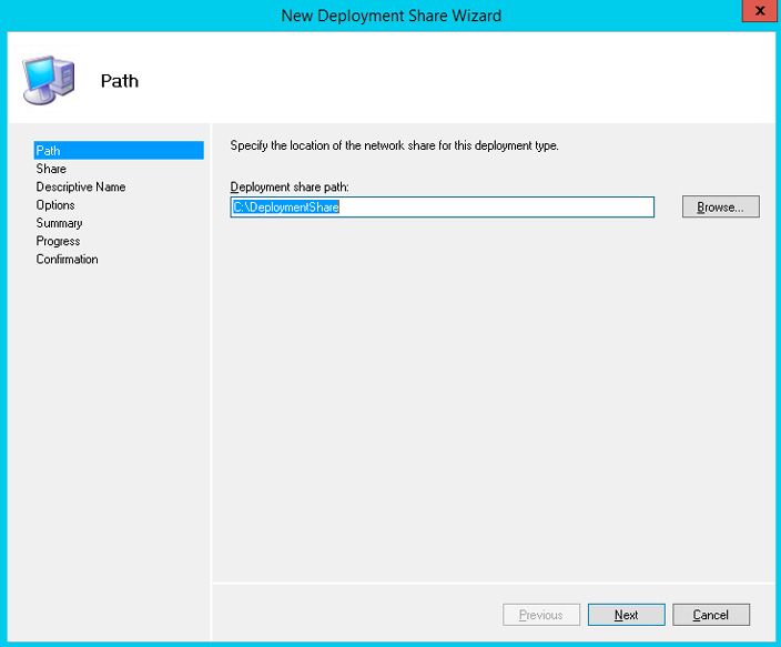
Change the deployment share name or leave it as default (DeploymentShare$) and click on Next.
Tip. Character “$” in the name of share means that the network shared folder is hidden from network users.
After the end of the wizard, open the folder C:\DeploymentShare.

This directory stores the images of operating systems, drivers, settings, and application packages. This folder is portable and it can be transferred to other MDT server.
Consider the main directories in MDT Deployment Share:
- Applications – application installation files are stored here (MS Office, Adobe Reader, etc.) which will be installed on the deployed system;
- Operating Systems – operating system image files;
- Out-of-Box Drivers – directory with device drivers;
- Packages – update packages packs;
- Task Sequences – task directory;
- Tools – a typical directory with various utilities that can be used in the deploying process.
To allow all network clients to connect to the created network share, you need in Share permissions of folder DeploymentShare$, add Everyone group with Read access permissions.

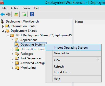
Next we need to import image of Windows 10. MDT allows you to import operating system image from the Windows source files, wim file or wds image.
Expand branch Deployment Shares -> MDT Deployment share. Right click on Operating systems item and select Import Operating System.
Select Full set of source files and choose drive with mounted Windows 10 ISO image.

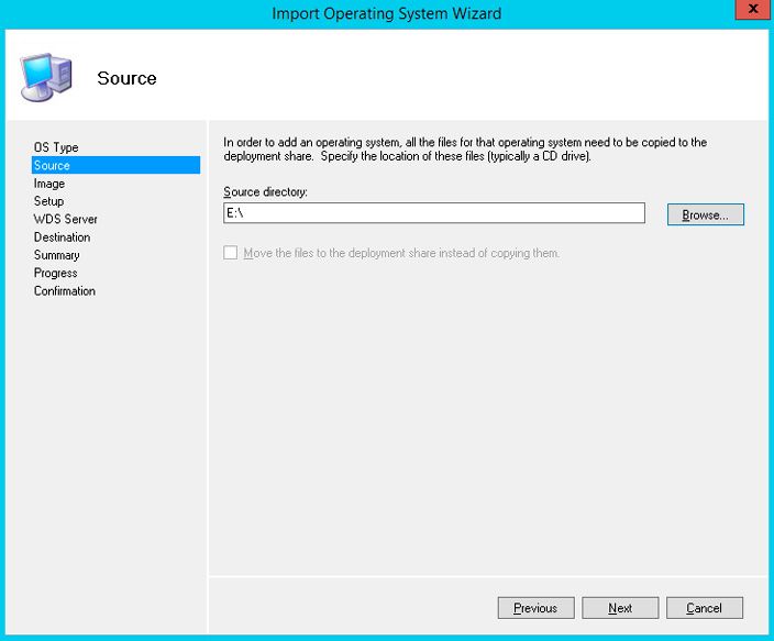
Enter destination directory name.

Wizard will copy Windows 10 source files to the folder C:\DeploymentShare\Operating Systems\Windows10Prox64.
Now in Operating Systems section you will see now the image of Windows 10 Pro x64.

Creating MDT Deployment Task Sequence
At the next step you must create new Task Sequence, which represents a bunch of instructions needed to be performed when deploying Windows (installation of drivers, applications, system settings, apps updates, run custom scripts etc.).
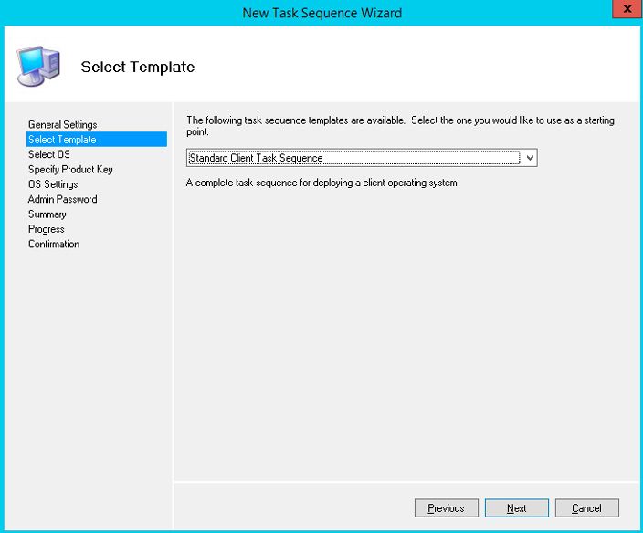
Right click on Task Sequences item and select New Task Sequence.

Enter DeloyWin10x64 for the Task sequence ID and “Deploy Windows 10 x64” as the Task sequence name.

Select from the drop-down list one of predefined sequence template. This time we are choosing Standard Client Task Sequence.
Select OS to deploy using this task sequence (Windows 10 Pro x64).

Specify product key. You can either skip entering Windows key or specify GVLK, MAK or retail Windows key.

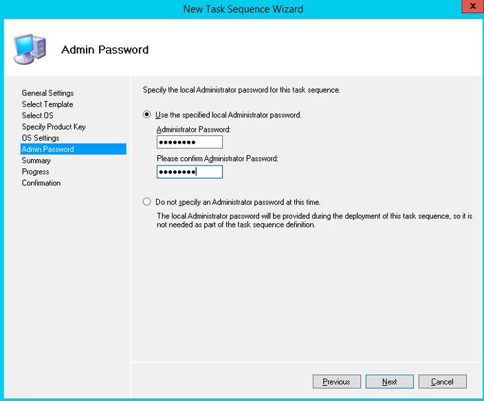
Specify local administrator password for the operating system being deployed.
Tip. Keep in mind, that the password is stored as a plain text in the Unattend.xml file.
Open properties of the created task and check that it is enabled and available to run on any platforms.

At Task Sequence tab you can see the sequence of steps for deploying operating system on the client (steps based on the previously selected sequence template). This time we will leave it all by the default.

Next run Update Deployment Share. MDT will generate boot images and configuration for deploying operating system.
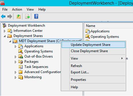
At first time (directory C:\DeploymentShare\Boot is empty) choose Completely regenerate the boot image and wait till the image generation will be finished (this can take a few minutes).

In folder C:\DeploymentShare\Boot ISO wim images will be generated, based on Windows PE for x86 and x64 platforms. You can use ISO files to directly boot physical or virtual machines, or WIM files to use it with Windows Deployment Services for PXE boot and network deploy of Windows Images.

Tip. We need only wim files (LiteTouchPE_x64.wim and LiteTouchPE_x86.wim) to use PXE booting.
Configuring Boot Images using Windows Deployment Services role
Now we need to configure WDS server role to respond on the clients PXE boot requests.
Open Windows Deployment Services console (Server Manager -> Tools -> Windows Deployment Services), expand Servers node, right click on your server name and select Configure Server.
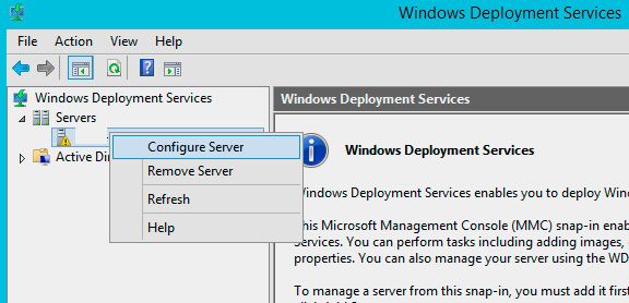
Select Standalone WDS Server, independent from an Active Directory.

Leave remote installation folder location by default (C:\RemoteInstall).
On PXE settings screen, select Respond to all client computers (known and unknown).

Tip. In an Active Directory domain environment its much more secure to select Respond only to known client computer.
Uncheck the box – Add images to the server now.

The green arrow icon on the WDS server says that it is up and running.

Next we need to add boot images to WDS server, created earlier by using MDT.
Right click on Boot Image –> Add boot image.

Browse to C:\DeploymentShare\Boot folder and select file LiteTouchPE_x86.wim and then LiteTouchPE_x64.wim.


As you can see, LiteTouch WindowsPE (X86) and (x64) images appeared in the list of WDS boot images.
And the last thing we need to do is open WDS server properties and go to the Boot tab.
To prevent accidental loading of clients through PXE and deploying Windows, safest require the user to press the F12 key to use PXE boot. So in PXE Boot Policy section select Require the user to press the F12 key to continue the PXE boot. If you select this option when starting the PXE boot, you will be prompted to press the F12 key to continue booting over the network. If the keystroke does not occur for a certain period of time, the PXE boot will be canceled and the computer will attempt to boot using the boot method next in the BIOS boot priority list.
Note. The option Always continue the PXE boot means that the PXE boot will continue without any need to press a key. The “Continue the PXE boot unless the user presses the ESC key” indicates that the network boot will continue if the user didn’t press the ESC key for a certain time.
Select default boot images for x86 and x64 architectures (including UEFI architecture).

All other WDS server settings leave by the default.
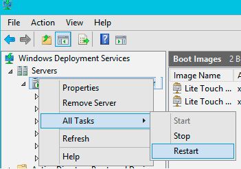
Restart WDS service via Console (All tasks ->Restart).
Important. WDS server and the client computer that we want to deploy via PXE must be placed in the same IP subnet (VLAN), like in our test environment for this article. If the client computer and WDS server are located on different networks, it is necessary to configure IP Helper and additional DHCP server options 60 and 67.
Adding Device Drivers to the MDT
With MDT, you can install any device drivers on your computers during the deployment of a Windows 10 image. Right-click the Out-of-Box Drivers folder and select New Folder.

Specify the folder name (you can create driver folders by OS version or by the computer model). Then right-click on the created folder and select Import Drivers. In the window that appears, specify the source directory, which contains the driver files (it is important that drivers are needed in unpacked form, i.e., in the form of a folder in which .inf files are located in). Click Next > Next > Finish.
Perform these steps for all devices for which Windows 10 could not find the driver (do not forget that there are 32 and 64-bit drivers for different versions of Windows 10).

After the drivers are added, it remains to update the deployment share. Drivers will be installed on the deployed Windows 10 computer automatically. There is nothing extra to do. The default simple PnP ID drivers detection method is used.
If a large number of drivers for various devices are added to your MDT server, then in order to speed up the OS deployment, it is advisable to link the hardware drivers to different device models and/or OS versions.
To do this, in MDT 2013 you need to use filtering with Selection Profiles. After importing the drivers, you need to create a selection profile for each driver folder. Then (Advanced Configuration > Selection Profiles > New Selection Profile > Windows 10 x64 and select the appropriate directory with drivers in Out of Box Drivers folder).
Add a custom Task Sequence in the Preinstall stage to your deployment Task Sequence with the type Inject Drivers.
Then in the Task Sequence settings at the Preinstall stage, select the correct profile and enable the Install only matching drivers from the selection profile option.

When booting over the network, the computer boots using the boot image obtained from the WDS server. If the boot image doesn’t contain the required network card drivers, then the computer won’t be able to connect to the WDS server to select and then boot the Windows 10 installation image. Therefore, for some computer models, you need to inject an additional network drivers using the MDT management console (to the LiteTouchPE_x64.wim and LiteTouchPE_x86 .wim images).
In addition, you can integrate drivers into a WIM image file or copy them into the $OEM$ subfolder, and specify the path to it in the autounattend.xml file.
It’s important to mention that the unattend.xml answer file can be added to the WIM image itself, by putting it in the %WINDIR%\Panther\Unattend folder, but for MDT you will still need a separate external file to run inside the Task Sequence.
Testing Windows 10 Deployment over Network
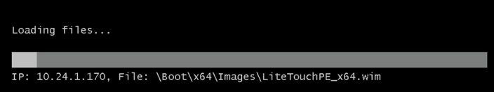
We are now ready to test the boot of network clients from WDS server over LAN (PXE boot). For this test we use a virtual machine running on VMWare ESXi hypervisor. Run VM and press F12 several times to begin network boot from PXE.
Press F12 for network service boot.

Tip. Because Boot screens on VMs appear very quickly, it is almost impossible to have time to press F12. So we need to set the highest priority to boot device Network boot from Intel E1000 in BIOS of VM.

Machine will connect to WDS server and show you a list of available Windows PE boot media. In standard Windows Boot Manager dialog select desired operating system to boot from. Select to boot Lite Touch Windows PE (x86).

The system will load over the network wim image file of WinPE environment and offer to begin the installation of Windows 10 using Microsoft Deployment Tool Wizard.
Click on Run the Deployment Wizard to install a new Operating System button to start the step by step wizard of Windows 10 Image installation on the client computer.

In our example it was also necessary to specify UNC path to the network folder DeploymentShare$ on MDT server (\\10.1.1.170\DeploymentShare$) and user credential to access it.
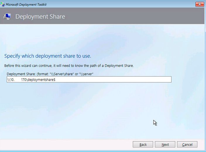
It remains to choose desired Task Sequence that you created earlier in your MDT 2013 (Deploy Windows 10 x64) and start a network deployment of Windows 10 Image on this computer.

In this article we showed you how to combine MDT 2013 and WDS server in order to create deployment infrastructure to deploy Windows 10 with MDT 2013.
How to Configure DFS Replication on Windows Server 2016 ?
Posted by on March 24, 2019
This manual describes how to configure DFS data replication in the Active Directory domain on servers running Windows Server 2016.
There are two types of Distributed File System (DFS):
- Namespace DFS – DFS allows you to create virtual directory trees that unite shared folders across the network. It is possible to configure multiple DFS namespaces. It uses simplified user access to geographically distributed files;
- Replication DFS – creates a replicated shared folder and tracks changes in files.
Installing DFS Namespaces and DFS Replication Roles on Windows Server 2016
Install the DFS Namespaces and DFS Replication roles on the two servers running Windows Server 2016 between which the replication will be configured.

Use the DFS Management console (dfsmgmt.msc) to create a new DFS namespace.
You can create a domain-based namespace or stand-alone namespace.
- Domain-based namespace – namespace integrated into the AD. Allows you to hide the DFS namespace server name from the users, simplifies the replacement of the namespace server as well as transfer the namespace to another server;
- Stand-alone namespace – allows you to create DFS structures without using an Active Directory Domain Services (AD DS). The high availability of the namespace can be achieved using a failover cluster.

Create a folder in the new namespace. Make sure that the new directory is accessible over the network by the path\\dfsnamespacename\foldername (in our example it is \\contoso.com\public\shareddocs).

Configuring DFS Replication Between 2 Servers Running Windows Server 2016
Now you can configure DFS replication. DFS Replication allows you to synchronize directories with files (replicated folders) between servers that are part of a DFS replication group. The servers into DFS replication group are connected to each other using DFS connections.
Changes are replicated using the Remote Differential Compression Algorithm (RDC). Only the changed parts of the files are replicated. DFS replication is performed asynchronously, i.e. at a specific point in time, sources may not be consistent.
It is necessary to distinguish between simple FRS replication (File Replication Service) and DFSR (Distributed File System Replication). DFSR appeared in Windows Server 2008, it became possible to use differential compression when performing some changes in the file, but not the entire file, are transferred over the network. In FRS replication, the entire file is copied.
DFS replication is advantageous to use folders between remote branches over slow WAN link for replicating.
When communication between replication partners is lost, replication stops. After the network is restored, replication will continue.
A replication group is a set of servers (members) that participate in the replication of one or more folders.
Before configuring replication, you need to add a network shared folder on the second DFS server. Open the DFS Management console, select the desired namespace, and select Add Folder Target from the context menu.

Enter the name of the shared folder and click OK (in our example this is \\host2\dfssharedocs).

You will be prompted to create a new replication group. Click Yes.

Tip. If you clicked No, then to create a new replication group in the DFS management console, right-click on the Replication section and select New Replication Group.
In the DFS Replication Configuration Wizard, you need to verify the name of the replication group and the directory you want to replicate.

Check the paths to the shared folders on the servers.

Select the primary member node on which the initial data is stored and from which initial replication will be performed.

As a rule, Full mesh is selected as the replication topology. In this topology all changes on one node are immediately replicated to all the others.

It remains to adjust the schedule and bandwidth that can be used to replicate data. Check the settings and click Create.
A message should appear after the successful creation of a new replication group.

This completes the configuration of the DFS distributed file system and data replication in it.
Try creating a new file in the shared folder on the one of the member server. If the file size is very large, its replication can take several hours or even days, depending on the bandwidth of the communication channel between DFS servers and the DFS replication settings.

If 2 users simultaneously edit (or create) the same file, then DFS replicates the version of the file that was changed (created) last. An earlier version of the file is stored in DfsrPrivate\ConflictandDeleted directory on the server that resolves the DFS replication conflict. In this case, an entry about the conflict that has occurred appears in the ConflictandDeletedManifest.xml file.
Tweaking DFS Replication
After creating a DFS replication group, you can change various settings to provide better performance.
In the DFS Management console, expand the Replication section, which contains all the replication groups.
Select the replication group you created. In the right window you will see 4 tabs:
- Membership – this is a list of network folders between which data is replicated;
- Connections – describes the topology of relationships between DFS replication partners;
- Replicated Folders – DFS folder settings;
- Delegation – replication group permissions.
On the Membership tab, note the Staging Quota value — 4 GB. What it is? When replicating, the DFS service uses intermediate hidden folders that store modified files that need to be transferred to replication partners. These files are stored on each server in a local folder DfsrPrivate\Staging.

On the Membership tab, open the properties of any folder and go to the Staging tab. As you can see, here you specify the path to the Staging folder and its maximum size (Quota). The default is 4 GB. In large infrastructures, it is desirable to increase the quota size to increase the performance of the DFS file replication service.
Microsoft recommends that this quota should be not less than the total size of the 32 largest files in the replication directory. The total size of the 32 largest files in the directory can be obtained using the following PowerShell command:
Get-ChildItem C:\SharedDOCS -recurse –force | Sort-Object length -descending | select-object -first 32 | measure-object -property length -sum).sum /1gb
If the staging quota for the DFS server is insufficient, events with EventID 4208 will often be recorded in the event log. In this case, it is recommended to increase the staging quota size by 20%.
Tip. Some admins believe that a file that is larger than the quota on the Staging folder cannot be replicated via DFS. This is not true. Such a file can also be replicated normally, just the replication process will take place in several stages (the file will be cut into several parts and transferred in parts), which will somewhat slow down the process.

On the Advanced tab, you can specify whether to save the files deleted by users in the ConflictandDeleted folder (it is very convenient to restore) and the quota for this folder (by default, it is also 4 GB).

To switch the DFS directory on a specific server to read-only mode, click the directory and select Make read-only. As a result, users won’t be able to edit or create files in this directory.

On the Connection tab, you can temporarily suspend replication to one of the servers in the DFS replication group (Disable), or start forced replication (Replication Now).

On the Replication Folders tab open the properties of any folder. The File filter field contains a list of file extensions that are not replicated between DFS servers. The default file extensions are .bak, and .tmp. You can add other types of file extensions that don’t need to be replicated, for example video (*.avi, *.mpeg), audio (*.mp3, *.wav), image files (*.iso, *.wim) or other file types.

To diagnose DFS replication, you can use system event logs, as well as the current (%windir%\debug\DFSR*.log) and archive DFSR replication log (%windir%\debug\DFSR*.log.gz).
Information about DFS replication settings on the server can be obtained using the PowerShell cmdlet Get-DFSRConnection.

Configuring DHCP Load Balancing on Windows Server 2016 …
Posted by on March 24, 2019
DHCP servers are one of the key elements of the network infrastructure. However, unlike DNS servers or domain controllers, before the release of Windows Server 2012, Windows Server didn’t have the integrated mechanisms for the DHCP role high availability and load balancing. Earlier the high availability task was solved by dividing the DHCP scope into two parts, each of which served its own server. But this approach had a lot of inconvenience, starting from the fact that all the settings needed to be duplicated between servers and ending with the fact that in case of a fault, a manual intervention would still be required.
How to Configure DHCP Load Balancing?
Starting from Windows Server 2012, the ability to create DHCP failover configurations has been added. In this article we will show you how to configure load balancing on a DHCP server running Windows Server 2016.
To ensure fault tolerance and load balancing, you need two servers with DHCP Server role installed. But before this, both servers need to assign the correct DNS names, static IP addresses and join the servers to the AD domain.
Install the DHCP Server role from the Server Manager console or using the PowerShell command:
Add-WindowsFeature DHCP –IncludeManagementTools

After installation, be sure to authorize a DHCP server in the Active Directory.

On one of the servers, add and configure a new IPv4 DHCP scope.

Then right-click on the root of the ipv4 or on a specific scope and select Configure Failover in the drop-down menu.

A wizard will appear prompting you to select the scopes for which you want to implement fault tolerance.

In the next step, you will be prompted to select a partner server. This can be any available DHCP server based on Windows Server 2016. In the domain network, you will see a list of authorized servers, or select the server using the Browse button.

It remains to choose the DHCP server operation mode, if necessary, correct some parameters and set a shared secret (the key phrase to create an encryption key).
Two failover modes are available for the DHCP server:
- Load Balance – two servers simultaneously issue IP addresses and options for clients in some subnet. Client requests to load balancing servers are distributed between two servers (you can set the desired percentage). This is the default operation mode.
- Hot standby – in this mode, the two servers operate in a fault-tolerant configuration, in which the active server is responsible for the IP addresses leasing and configuration information for all clients in the scope or subnet, while the secondary (standby) server takes over its functions if the primary server becomes unavailable. A server is considered primary or secondary in the context of an IP subnet.

Consider the available options:
- Maximum Client Lead Time – the time at which the partner server extends the lease of IP addresses to the clients of the second server if communication with it is lost;
- Load Balance Percent – sets the proportion of requests distributed between servers;
- State Switchover Interval – time after the loss of communication with the partner, when the server goes from the state of “connection lost” to the state “partner is disabled”;
- Enable Message Authentication – between servers, a secure communication channel is established using a passphrase.
In hot standby mode, the set of options is a little bit different:

- Role of Partner Server – allows you to select server roles. By default, the server on which the failover is configured becomes active, the partner is put into standby mode;
- Addresses reserved for standby server – part of the scope allocated to the standby server to serve new clients in the “lost connection” mode.
After selecting all the necessary settings, click Next. This is where the DHCP failover setup wizard is complete.
Only information about the issued IP addresses is replicated between partner servers; changes in the scope settings, including reservation, should be synchronized manually. To do this, in the DHCP console, click on the scope and select Replicate Failover Scopes.

Or you can start all scopes replication from the host1 using PowerShell:
Invoke-DhcpServerv4FailoverReplication -ComputerName host1.contoso.com
There is the following limitation in DHCP failover in Windows Server 2016: two DHCP servers per scope. You should remember and understand that the high availability of DHCP is implemented not on the basis of servers, but on the basis of scopes. If a single server contains multiple areas, then it can be a part of several high-availability configurations. In addition, the failover relationship for IPv6 scopes is not supported.
How to Set Up and Configure Failover Cluster On Windows Server 2016 ?
Posted by on March 24, 2019
Failover cluster is a feature of Windows Server that allows you to group multiple independent servers into a single failover cluster with high availability and scalability.
In this article, we will show you how to create a simple three-node failover cluster configuration running Windows Server 2016 Datacenter or Standard editions. These can be physical servers or virtual machines.
In previous editions of Windows Server, it is imperative to join all servers into one Active Directory domain. Starting from Windows Server 2016, this is no longer a requirement, you can organize a failover cluster even on servers in a workgroup (in this configuration, you can cluster only SQL server, File server or Hyper-V roles). If you plan to use Failover Cluster to provide fault tolerance for the Hyper-V virtual machines, the same CPU model must be used on all servers of the cluster (only Intel or only AMD), otherwise live VM migration between nodes of the cluster will become unavailable.
Each cluster node must be connected to at least two networks: a local area network (LAN) and a SAN (Storage Area Network). You must configure static IP addresses for all servers that you want to add to the cluster. You also need to ensure that all servers can access shared storage via FC, SAS, or iSCSI (iSCSI protocol version is not lower than iSCSI-3).
Open Server Manager and install the Failover Cluster feature. You can also install this feature using PowerShell command:
Install-WindowsFeature Failover-Clustering –IncludeManagementTools
This component must be installed on all servers that you want to add to the cluster.
After installing the role, open the Failover Cluster Manager console.
Select Create Cluster in the context menu.

Specify the names of all nodes that you want to add to the cluster (by name or IP address). In our case, these are the three servers: win-agnode01, win-agnode02, win-agnode03. Click Next.

Then specify the name of the cluster and the clusters’ IP address (this IP address should not be busy). This name and IP address will be used to manage and configure the cluster.

Next, it will launch the cluster configuration validation wizard and start the cluster creation process. You can read the detailed cluster creation log.
If all three cluster nodes are configured correctly, the wizard must successfully create a new cluster.

Now in the Failover Cluster Manager snap-in, a new cluster should appear with the name cluster1.
To ensure correct operation of the cluster, you need to configure the quorum. By default, each cluster node has one quorum vote. In addition, a quorum witness (if configured) has one additional quorum vote. You can configure one quorum witness for each cluster. Each item can cast one vote to determine if a cluster can be started. The presence of a quorum in a cluster for its proper operation is determined by the majority of voting members who are active members of the cluster.
You can configure the quorum witness mode by right-clicking the cluster name and selecting More Actions > Configure Cluster Quorum Settings.
If there is a number of nodes in the cluster, you will need to configure the quorum witness resource. In Windows Server 2016, you can use as a witness resource.
- File Share witness — (shared SMB folder);
- Disk Witness — shared disk (with simultaneous access to it from all nodes);
- Cloud Witness — cloud disk resource in Azure (blob storage).
In our case, there are 3 nodes in the cluster, therefore quorum witness can be not configured.

Select the Nodes section. As you can see, three servers have been added to the cluster, and all of them are available and working normally (Status – Up).

In the Storages section, you can add disks to the cluster.
Now, in the Failover Cluster Manager console, you can add the failover capability of one of the proposed roles, Hyper-V virtual machines, or shared disks.
,

By default, on Windows Server 2016, you can provide high availability for the following roles:
- DFS Namespace Server
- DHCP Server
- Distributed Transaction Coordinator (DTC)
- File Server
- Generic Application
- Generic Script
- Generic Service
- Hyper-V Replica Broker
- iSCSI Target Server
- iSNS Server
- Message Queuing
- Other Server
- Virtual Machine
- WINS Server

